Updated 2018/12/23
There are many perks to working from home. The 30 second commute, the coffee on tap and the autocratic control over the air-conditioning make it ideal, provided one has the mental strength to get work done surrounded by myriad distractions and no-one but oneself to answer to. There are, however, some downsides. In this world of Amazon Prime 2-day shipping, being able to guarantee that someone will be home to receive your toilet-paper delivery is a great boon but, ensconced in your home office, a podcast in the background to simulate human contact, who among us could hear the doorbell when the bog-roll supplier does finally arrive? Enter the DIY Internet of Doorbells (IoD), a cheap and cheerful foray into the world of turning everyday appliances into a potential botnet.
I had originally considered using some flavour of Raspberry Pi to do the doorbell monitoring work but the thought of relegating an entire linux computer to watch a single pin seemed wasteful at best. So I turned to every maker’s favourite WiFi swiss army knife, the ESP8266, which I could pick up at my local hobbyist electronics store for R90 (under 7 freedom dollars) and seemed a much better fit. I had never used the ESP8266 before though so this was an opportunity to both add a new tool to the arsenal and practice going through the design, prototyping and implementation processes as quickly and effectively as possible.

After a trip to the aforementioned store, a pair of ESP8266s in hand, the first step was getting one powered up and talkative. As usual my first thought was the Raspberry Pi which has the 3.3V pins necessary to not fry the fragile ESP but then I remembered the Teensy 3.2 I still had after some contract work I had done a year before. The Teensy 3.2 also has the requisite 3.3V IO as well as a generous 250mA 3.3V supply pin that will happily power the ESP for the sort of tasks I needed it to do. After familiarising myself with the Arduino IDE again and blinking an LED on the Teensy I found the most promising diagram I could find online and connected up the ESP. Setting up the Teensy for serial passthrough was simple enough with just one hiccup where the Arduino serial line endings meant that the device responded to every AT command with an indignant ‘ERROR’. Non-printing characters tamed, I set about researching how to best turn the ESP from a WiFi serial bridge to a fully fledged micro-controller. In 2018 there are quite a few options to choose from in this respect, NodeMCU, Espressif’s own IoT SDK and Arduino seemingly the most popular options. Seeing as I had the Arduino IDE open in front of me, the logical option seemed to use the Arduino Core lovingly produced and supported by the community.
Flashing my first Arduino sketch to the ESP held its own pitfalls and learnings. Many how-tos, forum posts and blogs mention the various voltage level combinations for the different boot modes but the information is often garbled, related to different modules with fancier circuitry or featuring different pin naming schemes. Eventually I found this guide which in my mind is the absolute best resource for starting out with the ESP and it taught me the necessary pushbuttons and sequences to get the it to accept my binary file. Flashing procedure perfected, the hard work was pretty much done due to the expansive examples provided with the Arduino Core plugin; all I needed to do was modify the HTTP Client example to connect to my own WiFi network and send a local network GET whenever pin 0 went high.

But where does that local network GET go I hear you ask? This project is meant to be the first node in an entirely sense-able and controllable smart-home and to that end I needed some sort of hub. That means that finally, at the third time of asking, a Raspberry Pi gets involved. I already had a general purpose RPi sitting in a 3D printed VESA mount that does general tasks like serving files from a HDD, acting as a KODI media centre, updating my IP to duckDNS, etc, so I created a new directory called home-auto, installed the Express framework and put together a tiny node server with a single endpoint named ‘doorbell’. Luckily in a previous project I had already registered a Telegram bot for a Telegram connected Raspberry Pi camera (who I am sure will feature on this blog in the future) so it was a simple matter of sending a Telegram message from my bot every time ‘doorbell’ is called from my local network.

Software entirely done we finally arrive at the bane of Arduino jockeys the world over, analogue electronics. My doorbell is a relatively simple affair: two wires supply 12VDC(ish) to handset in the house, two wires connect the handset to the intercom with button outside and a final two wires connect the handset to the gate lock. Poking around with a multimeter showed that one of the wires to the intercom sat at ~5VDC when idle, ~2.5VDC when the intercom was pressed by a long suffering family member and shot up to almost 12VDC when the handset was lifted up. I also saw a worrying 23VAC reading on the supply lines and 6VAC on the intercom lines. The last points were important to note when protecting my circuitry from releasing its jealously guarded supply of blue smoke. My best guess at how the doorbell works is that the sound from both microphones is transmitted along the wire as an AM signal on top of the DC component and the handset has a threshold detector for when the intercom button drops the DC from 5VDC to 2.5VDC that will trigger the bell. Finally the jump to 12VDC stops the bell from deafening the unsuspecting home-owner should they put the receiver to their ear at the same time as an impatient guest presses the intercom button for a second time because the voltage will then not drop below the threshold as long as the handset is off the cradle.
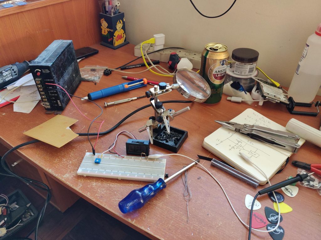
Armed with this info I set about designing a circuit that would take the 5-2.5V drop and convert it to a lovely 0-3.3V edge for the ESP and power the ESP at the same time. Opting for familiarity and expedience I deciding on a comparator based on the ubiquitous LM358 op-amp, a 0.23 ratio voltage divider to bring the the up-to-12VDC bell signal down to safe levels, a threshold of 0.77V and an LM1117 to supply both the op-amp and the ESP with room to spare. Diodes between the supply and the regulator and the bell signal and the comparator protected against any unwanted AC components reaching my circuit. Bench tests of the first iteration showed that, while the threshold detection worked fine, the LM358 could only manage a maximum output of 1.95V which, after consulting the internet, was below the ESP’s threshold for considering the pin HIGH. This called for an inverting BJT buffer that could go almost rail to rail which I added to the comparator’s output. Satisfied, I soldering the components to some stripboard and wired them up to the handset. Unfortunately after a seemingly successful start I started to get inconsistent operation with the device sometimes sending false alerts and sometimes refusing to send any at all after a power cycle. Poking around on the board with a multimeter when it was in it’s non-responsive mood I discovered that the buffer’s output was sitting at 1.6V instead of the 0V or 3.3V I was looking for. This I realised was because the 10k resistor I had between the comparator and the base of the 2n2222a was putting the BJT into its linear zone instead of into saturation like a had wanted. Dropping in a 1k resistor solved this problem which only left me with the false triggers. Without an oscilloscope I could only guess at what was actually happening at the comparator input but I assumed that some noise, audio or AC component was dropping below my threshold so with very little calculation or forethought I soldered a 10uF capacitor on the input and called it a day. Re-installing the circuit showed that my guesses had been correct and my telegram messages where coming through barely a second after ringing the bell without any false triggers or lock-ups.

Circuit pre fixes 
Unfortunately I had under-estimated the empty space in the receiver body and couldn’t hide the circuit inside so the circuit will be displayed proudly above the handset until I take the time to 3D print an enclosure. 
The final circuit, hand drawn for authenticity
All in all I am happy with my first foray into smartifying my home. Over time I would like to install an RPi camera with a zoom lens pointed at the gate so the doorbell script can grab a picture of the bell ringer to send along to my phone. I am also considering a mosfet to actuate the gate lock although I can’t think of a reason for me wanting to let someone in to my garden when I’m not home. Finally I wouldn’t mind setting up some sort of cell/VOIP situation that I could call and would inject my voice into the intercom signal in case the FEDEX truck arrives while I’m out so I can ask them to wait until I arrive but short of actually setting up a cell modem I can’t think of any other voice service to use.
Update 2018/12/23
As happens far too often and despite my best intentions, the story was not quite over. Once installed, the device was plagued by intermittent issues: sometimes it would false trigger, sometimes it would fail to start up entirely and sometimes it would seemingly work fine only to go silent after a few hours. Something needed to be done but the constant desoldering to get the device connected to the programmer again was getting me down so I needed a better plan. The better plan was two-fold: first I soldered headers on to the board so that the ESP could be taken on and off with ease, then I dove head first into the wondrous world of OTA programming.
The official Arduino libraries have included OTA for some time now and true to form the folks over at ESP2866 Arduino Core ported the feature over to the ESP with a few example sketches to boot. Imagine my dismay then when I flashed over the example code only to find that the network port that should now be available was nowhere to be seen? Much Googling taught me that the device advertised itself on the network using mDNS and many forum posts and stackoverflow answers suggested that perhaps my router was the roadblock I was experiencing. Sadly no matter which settings I tweaked or how many hotspots I created I could not get the device discoverable and I lost far too many hours in futile troubleshooting. The answer, in the end, lay in the beta software I was using. It turns out that between the beginning of the project and this point, the ESP8266 Arduino Core had progressed from 2.5.0 Beta 1 to 2.5.0 Beta 2 and after installing that, all my OTA troubles disappeared and my device was happily flashable over the network.
So now I had a quickly removable module and a the ability to program in situ but I was still no closer to diagnosing the issues with the board itself. The diagnosis eventually came to me at the bench power supply after trying to turn the board on for the umpteenth time only to find it non-responsive again after a brief flash of the LED. The brief LED flash was what gave the game away, as I recognised it as the same flash that happened when I use the pushbuttons to get the device into programming mode. It turns out that my design held GPIO_0 normally low which incidentally is exactly how to boot in programming mode instead of bootloader mode. My first instinct was to switch to GPIO_2 which I dutifully did, even going so far as to add a series resister to protect the pin should it ever be accidentally set as an output. This approach was doomed however as on my board GPIO_2 houses the built-in LED which, coupled with my series protection resister, held the pin at Vcc/2 when it should have been low. Loath to remove the resistor, I switched back to GPIO_0 knowing that I would need to carefully place Vbell wire to set the correct logic level before powering on the device but at least now I had built in protection as well. The other fixes/changes were pulling up ENABLE and RESET (which I should have done from the beginning and were almost certainly the source of the random restarts and thus false triggering, and adding an LED and software heartbeat, the LED heartbeat so I can see at a glance whether the device was running and a software heartbeat to ping the server which I could use in the future to track the online status all of my network connected devices.
The device has now been running for a few days with very few issues however this saga is not complete: should the power to the handset get reset, GPIO_0 will invariably be low and the device will boot in to programming mode again. I have wracked my brain for an elegant solution that would pull GPIO_0 high at boot irrespective of the state of Vbell but so far I have come up dry. Let me know in the comments if you have any ideas.
Comments
- Building An ESP8266 Doorbell On Hard Mode - The Best of Everything - […] It certainly seems as though it should be an easy enough project; all [Miguel De Andrade] wanted was to receive…
- Building An ESP8266 Doorbell On Hard Mode – MasMaz - […] It certainly seems as though it should be an easy enough project; all [Miguel De Andrade] wanted was to receive…
- Building An ESP8266 Doorbell On Hard Mode – Sloppy Laughs - […] It certainly seems as though it should be an easy enough project; all [Miguel De Andrade] wanted was to receive…
- Building An ESP8266 Doorbell On Hard Mode – Hack A Day - […] It certainly seems as though it should be an easy enough project; all [Miguel De Andrade] wanted was to receive…
Ron Hudson
January 8, 2019
This is a great write up. I know the struggle well! I would encourage you to checkout Home Assistant or “hass” it’s a great openspurce hub for all these sorts of things.
I’d also recommend looking at espeasy and mqtt. Espeasy is a really great esp8266 firmware that can send mqtt and does a lot of great stuff.
As for hardware. I’ve used the ESP-01. I even did a YouTube video on how to use it with arduino ide. But the proto boards with usb builtin are so much easier. Checkout the d1 mini.
As for your camera I think it can be done with an esp32 or maybe a d1 with an sdcard shield?
Finally micropython and circuitpython are fantastic alternatives for coding all these.
Roman
January 8, 2019
Nice post, thank you for sharing. When I need several GPIOs, I use ESP12. But many times we need just one, and the temptation to use a ESP01 is big. I wonder why they put the GPIO02 and not GPIO04. But, that is what we have. The solution I found, is to solder a very tiny wire directly on the ESP8266 chip. GPIO04 and 05 are located on the corners of the chip, so I very bad solder like me can do it very easy. After that any epoxy glue will finish the job. I have like 10 ESP01 running in my house with this “hack”, and for me was the only bullet proof solution.
But if you want to stick to GPIO00 you can try some .1uF capacitor in series with the GPIO… should work, what do you think?
Ed
January 8, 2019
Use gpio1 or gpio3 (resp tx and Rx)
David
October 2, 2019
Hi, thank you for this interesting article. I’m trying to use why you made for my on apartment intercom but I’m not so good at electronic. Can you tell me what is the black chip with 8 pins in the middle on the board ? Thanks !